MagSafe Mesh Node
This is a case for the RakWireless WisBlock Mini, turning it into a personal mesh node that sticks to the back of a MagSafe-compatible phone.
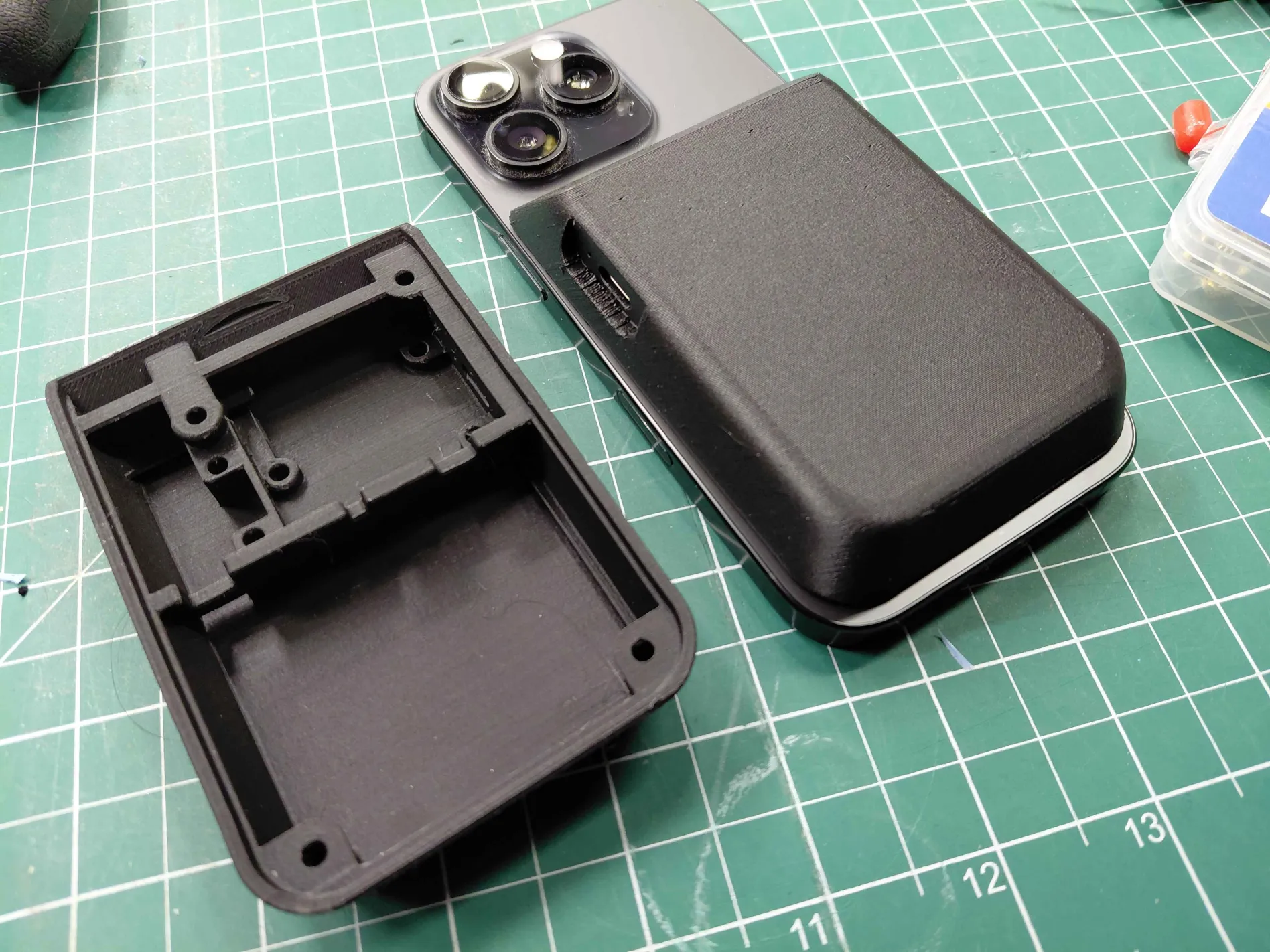
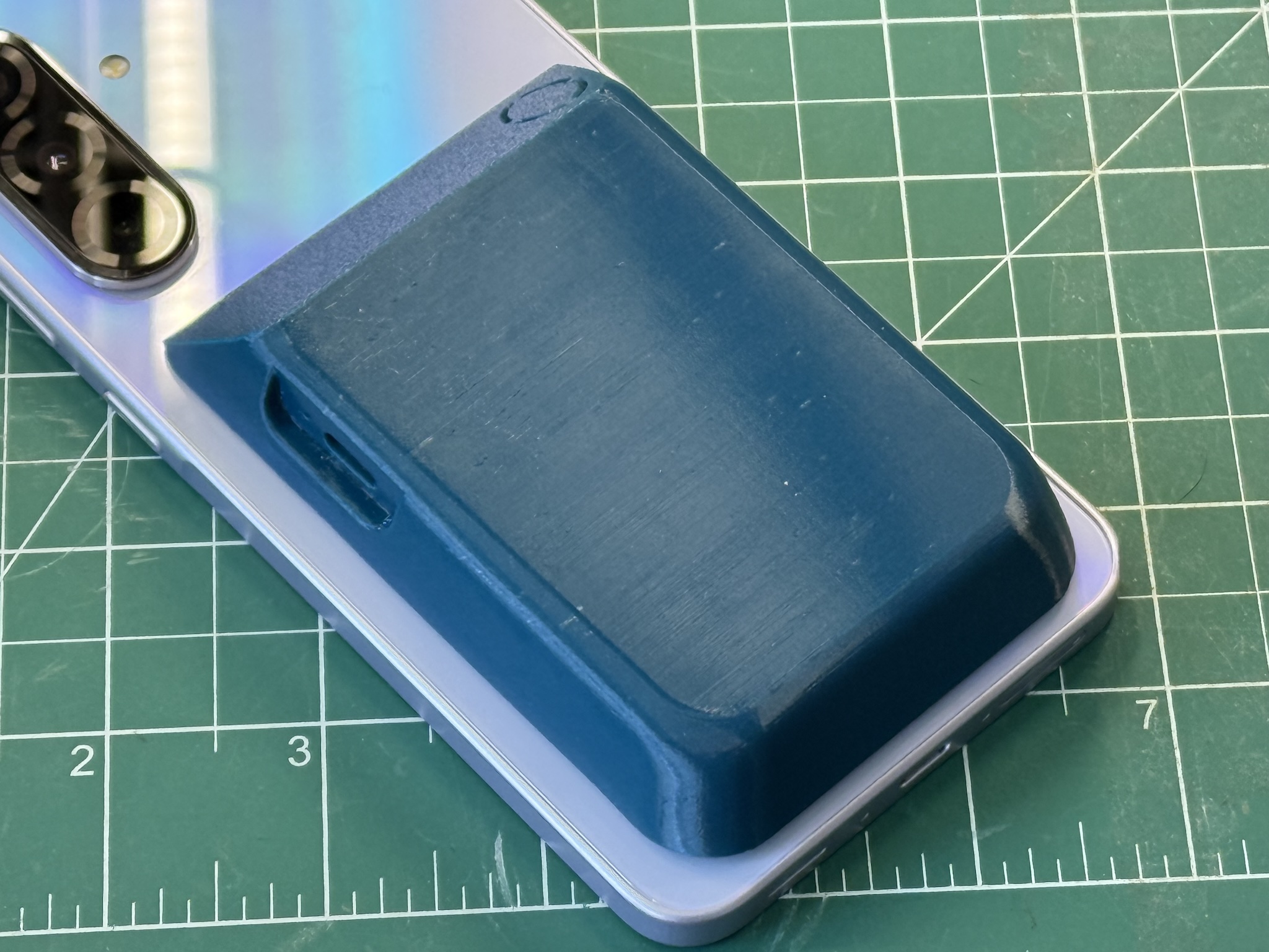
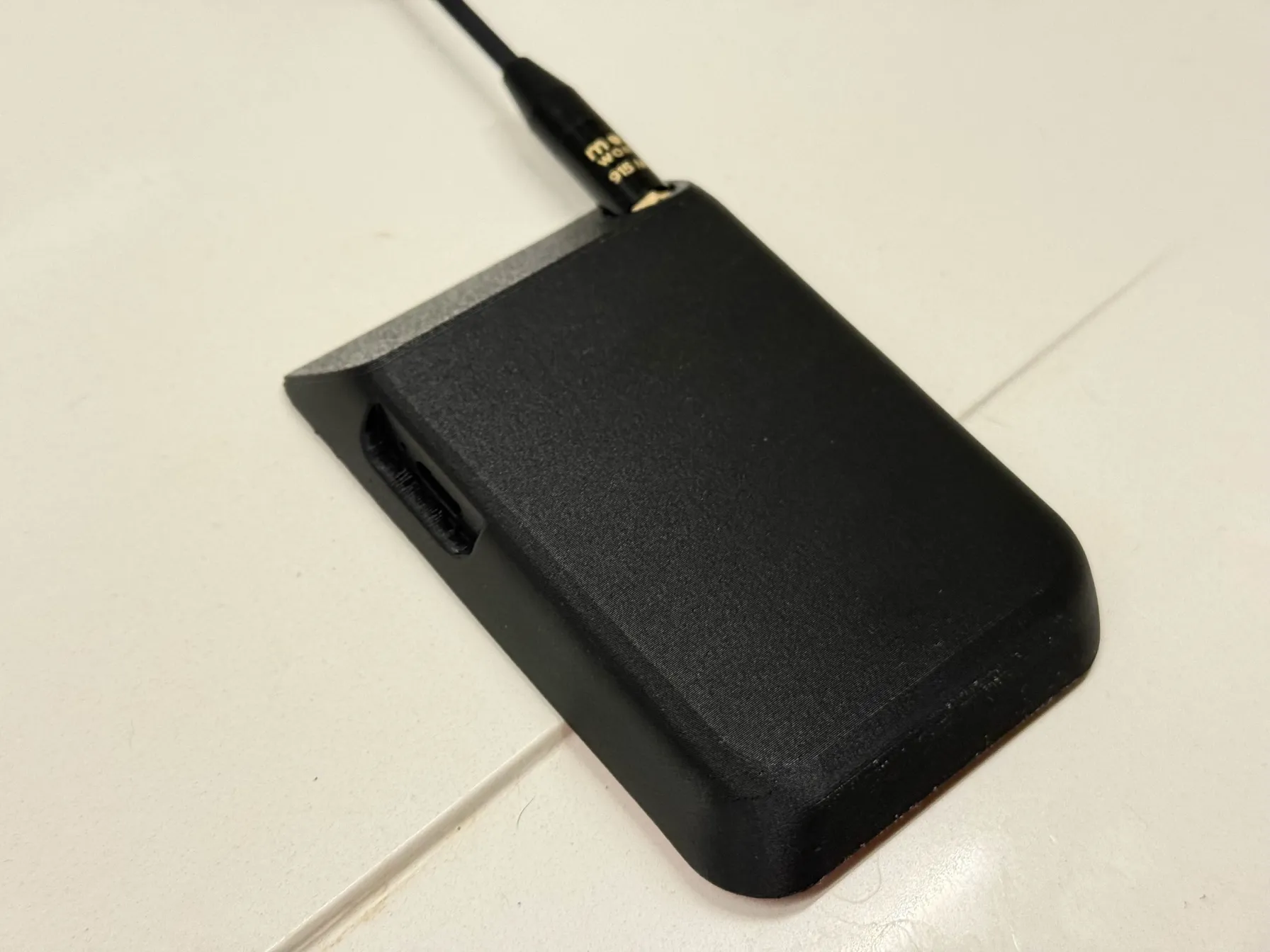
It’s inspired by this build and uses mostly the same parts, reworked for a more rounded shape, easier assembly, a hidden power switch, and support for more common battery sizes. It also makes the switch and external antenna optional. (IMO, an external antenna ruins the pocketability and contradicts the whole point of a MagSafe node.)
I developed this build with the help of the NYMesh group, and we used it for a workshop at NYC Resistor. It proved to be an excellent introduction to common making skills, involving 3D printing, basic soldering, and small parts assembly. The end result is a functional, attractive, and well-performing mesh node for Meshtastic or MeshCore.
The instructions and STL file are © 2026 by Alec Perkins K2XAP and licensed under CC BY-SA 4.0 ![]()
![]()
![]() .
.
Printed parts
Print settings
- PETG filament (referral link)
- 0.40 mm nozzle
- 0.10 mm layer height
- support enforcement under the rectangular patches of the cover plate
The fine layer height will take a long time to print but produce the best result (nearly 5 hours on a Prusa MK4). Yes, the case is at an angle like that. Don’t try to lie the case flat, the angle makes for the best surface quality, avoids supports, and aligns the layers in the best direction for strength.
Optionally enable fuzzy skin on the exterior surface of the case for a nice effect.
Bill-of-materials
If you would find it helpful to have the non-printed parts available as a packaged kit to purchase, let me know!
1x 3D printed case
1x 3D printed cover plate
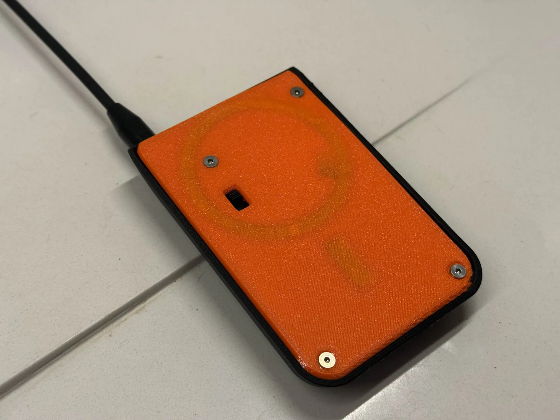
1x 3D printed magnet cover circle
1x 3D printed magnet cover strip
1x RAK Mini starter kit, includes:
- 1x RAK 19003 baseboard
- 1x RAK 4631 core module
- 1x u.FL–PCB 915 MHz antenna (for LoRa)
- 1x u.FL–PCB 2.4 GHz antenna (for Bluetooth)
- 1x u.FL–SMA pigtail (for LoRa external antenna)
- 5x pan head screws
6x threaded inserts, M2.5xD3.5xL4
6x M2.5x4mm countersunk machine screws
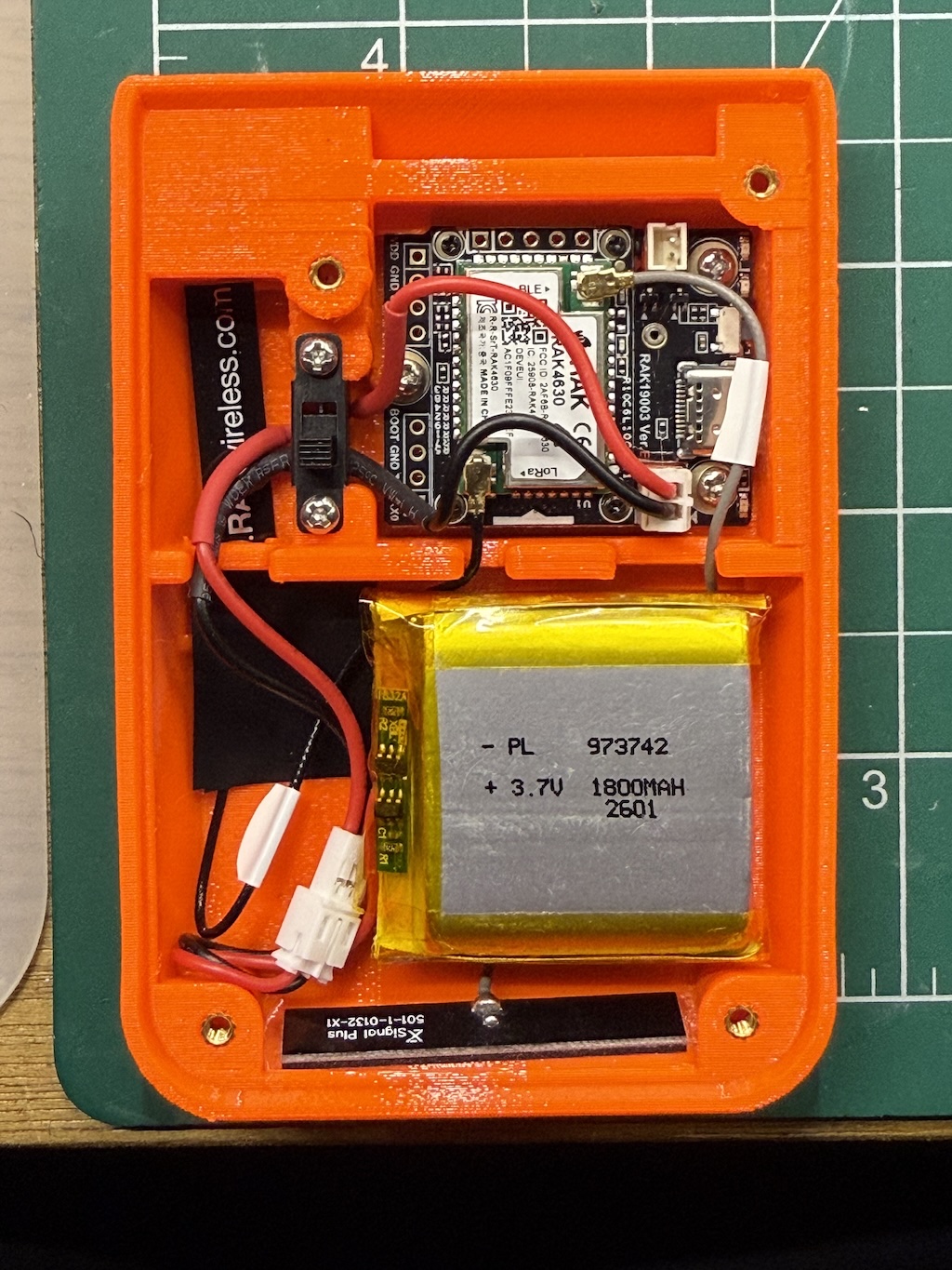
1x LiPo battery: 804050 recommended, 104245 or 973742 possible
1x magnet sticker set
4x foam stickers, 2mm thickness
PVC tape AKA electrical tape
"Cat Tongue" or similar grip tape
(optional: switch) 1x slide switch, 5mm knob
(optional: switch) JST 2.0 connector male
(optional: switch) JST 2.0 connector female
(optional: switch) 2x heatshrink tubing
(optional: ext antenna) 1x Muzi whip antenna
Tools needed
- Phillips screwdriver
- craft blade (Xacto)
- soldering iron
- soldering station/fume extractor
- heatset insert tips
- wire strippers
- snips
- hot air gun
- tweezers
- SIM ejector tool or paperclip
Instructions
Prepare printed parts
- Print the four pieces in PETG using the single STL file and the above print settings.
- Use a heat gun to remove any stringing.
- If using the switch, cut away knockout from the cover plate and clean up sprue.
- If using the external antenna, cut away knockout from case and smooth the opening.
- Remove the support patches from the two rectangular sections of the cover plate.
- Using a soldering iron with heatset tips at 250C, press in the 6 heatset inserts into the case.
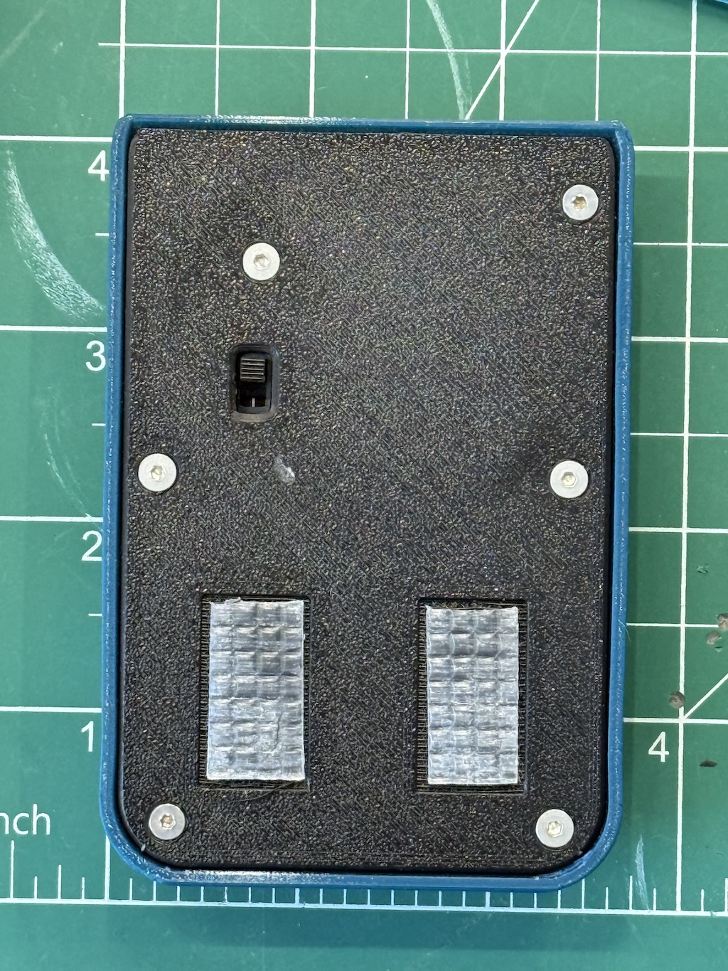
Prepare cover plate
- Check magnet sticker polarity against phone.
- Peel away backing and insert magnet into groove of cover plate.
- Double-check magnet polarization against phone.
- use tweezers to extract magnet and flip if needed.
- Apply 3D printed magnet cover circle and strip to backside of sticker.
- Apply grip tape sections to the rectangular sections of the cover plate.
- This helps prevent the case from pivoting on the phone.
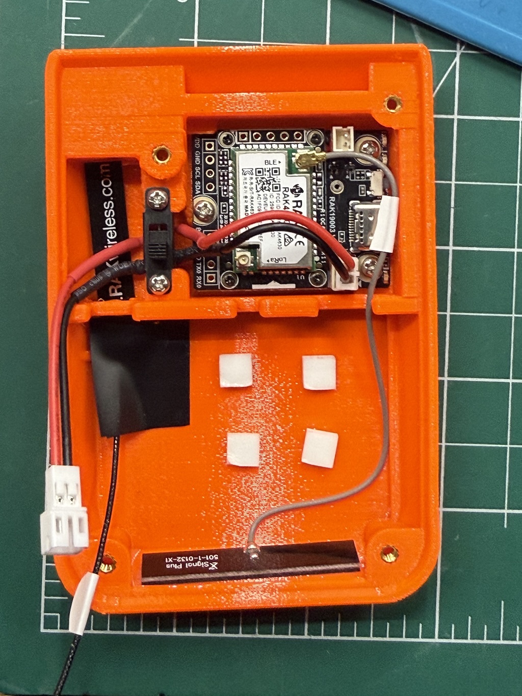
Prepare battery and switch subassembly
Caution: mind the battery polarization! Most batteries come with the positive (red) side opposite the RAK baseboard—on the baseboard positive (red) is toward the USB port when viewed from the top.
You can flip the pins on the female JST connector that goes from the switch to the board. The pins on the male JST connector from the switch should match the battery. You may want to flip all of them to match the board, for consistency.
If skipping the switch, you may need to flip the pins that come directly off the battery.
With the back of the switch (the pins) facing you:
- Snip the bottom pin, this will be the off position.
- This is not strictly necessary for the switch to function but will allow for more room for the wiring.
- Bend the top pin to the left
- Bend the middle pin to the right
- Cut the JST connector wires to length, roughly half but dry-fit in the case to confirm
- Avoid excess length that could make it difficult to fully close the cover plate
- Strip ends of red wires ~3mm, black ~10mm.
- Cut the red heatshrink tube in half
- Slide red heatshrink tube over red wire of female JST connector, solder this wire to top pin with the connector going to the left.
- Slide red heatshrink tube over red wire of male JST connector, solder red to middle pin with the connector going to the right.
- Slide black heatshrink tube, solder black wires together directly.
- Position heatshrink tubing over solder joints as much as possible, use heat gun to shrink into place.
Assemble
Install node module
- Insert the RAK Mini board into the top portion of the case, USB port facing the cutout for it.
- Secure the board using 3x pan head screws, threading directly into the plastic.
Install LoRa antenna
If using external antenna:
- Insert SMA connector into hole at top of case.
- Route cable with u.FL connector toward the battery compartment.
- Connect u.FL connector to LoRa port on the 4631 module.
- Screw on the external antenna to the SMA connector.
If using internal antenna:
- Trim the label on the cable, if any.
- Slide internal PCB 915 MHz antenna into the slot under the middle brace, with the top of it tucking under the small protrusion at the top of the case where the hole for the external connector is.
- Secure with a small patch of PVC tape at the base of the antenna.
- Connect u.FL connector to LoRa port on the 4631 module (farther from the USB port).
Install Bluetooth antenna
- Trim the label on the cable, if any.
- Remove the sticker backing of the 2.4 GHz antenna.
- Stick the 2.4 GHz antenna to the bottom of the case, wire facing away from the opening.
- Run the wire under the ridge along the right side of the case and through the cutout in the middle.
- Connect the u.FL connector to the BLE port on the 4631 module (closer to the USB port).
Install switch
- Insert the switch into the space between the board and the antenna.
- Make sure the off position is down.
- Tuck the black wire in the gap left by the removed pin.
- Route the female JST connector to the right and connect to board.
- Route the male JST connector left and down through the cutout toward the battery.
- Secure the switch using 2x pan head screws, threading directly into the plastic.
Install battery
- Double check polarity of everything.
- Apply four foam sticker squares to case, remove backing
- Insert battery so the JST connector is coming from the bottom left corner.
- Make sure the antenna cables are routed behind the battery so they won't get pinched by the cover.
- Double check the antennas are securely connected.
- Make sure the switch is in the off position.
- Connect the female JST connector from switch to male JST connector from battery.
- Tuck connector into case.
- Turn on switch and observe green light from board.
Install cover
- Lay cover with magnet on top of case.
- Secure with 6x countersunk M2.5 screws.
- Ensure the heads of the screws are completely flush or below the surface of the cover, so they do not scratch the phone.
Configure
- Update the firmware, selecting RAK WisBlock 4631: Meshtastic or MeshCore.
- Use the SIM ejector tool or paperclip to double tap the reset button.
- Connect to phone and configure as desired.